Journey中的沙丘渲染及其Shader实现
- 作者:admin
- /
- 时间:2018年03月06日
- /
- 浏览:12663 次
- /
- 分类:厚积薄发
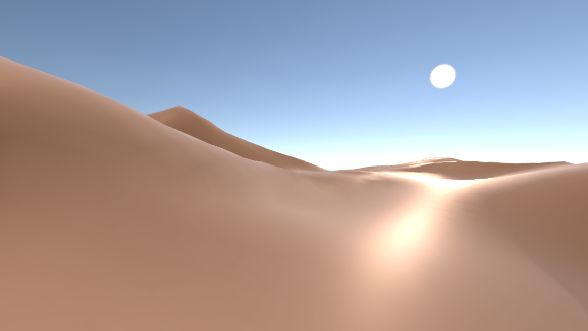
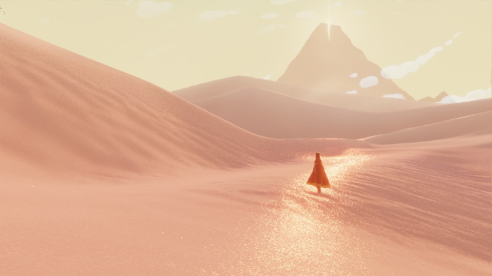
在写这篇文章之前,我先给大家展示下,下图是Journey里面的沙丘渲染是很久之前一直想做的,但总是没时间。最近因为项目中在做一个沙丘的场景,所以趁这个机会来做一下。
在这里事先声明,在场景再现中所用到的技术基本上是在尊重Journey原作的精神下进行的个人创作。由于素材,参数以及个人能力等原因,要完全重现Journey里面的场景十分困难,也没有意义。另外在制作时不会考虑开销,一切以效果为重。本作仅希望通过场景复原过程分享与收获一些风格化渲染的经验。
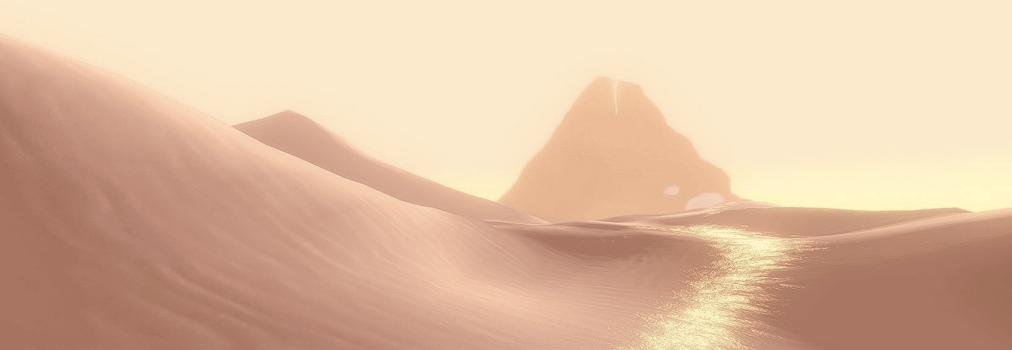
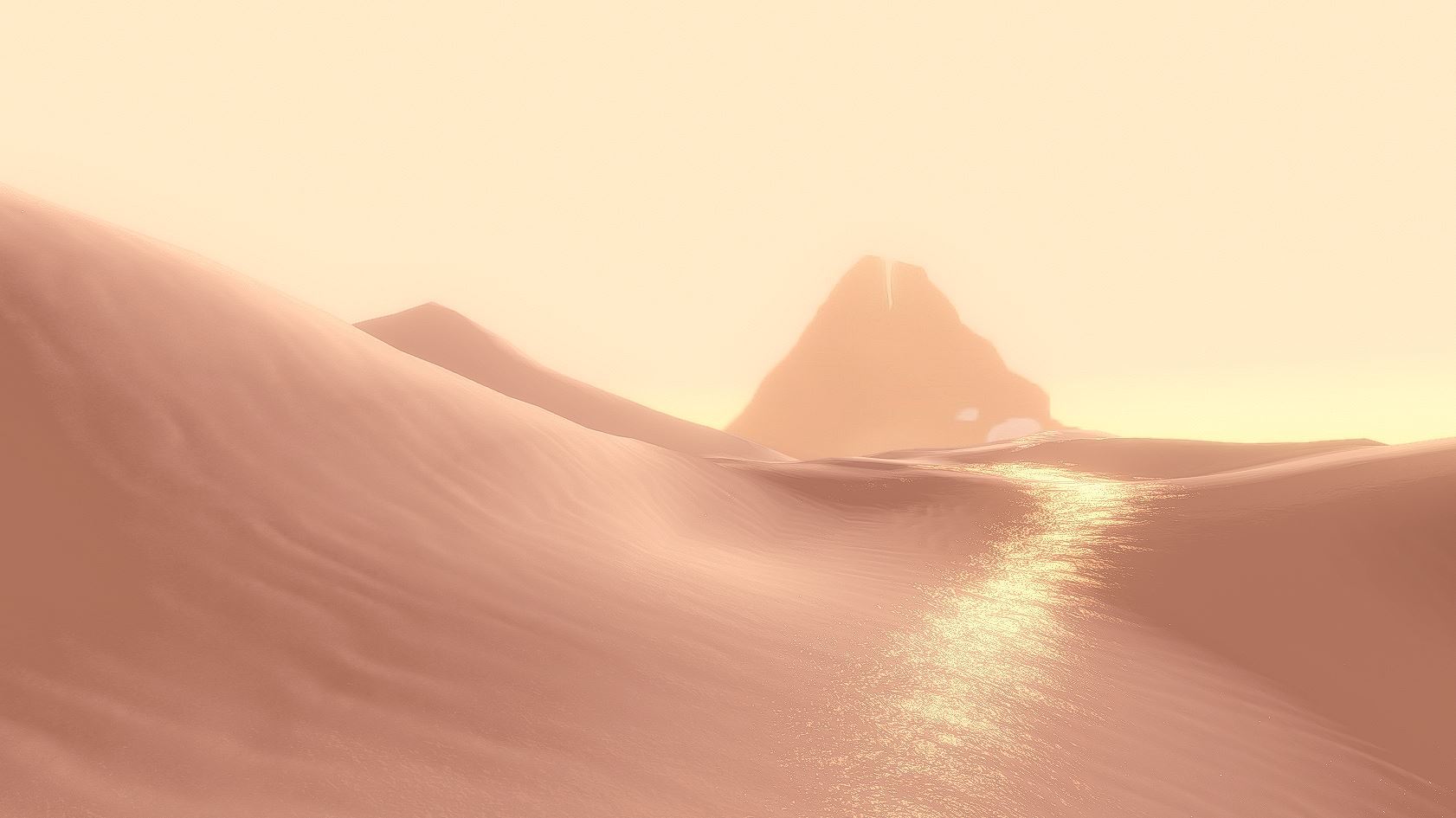
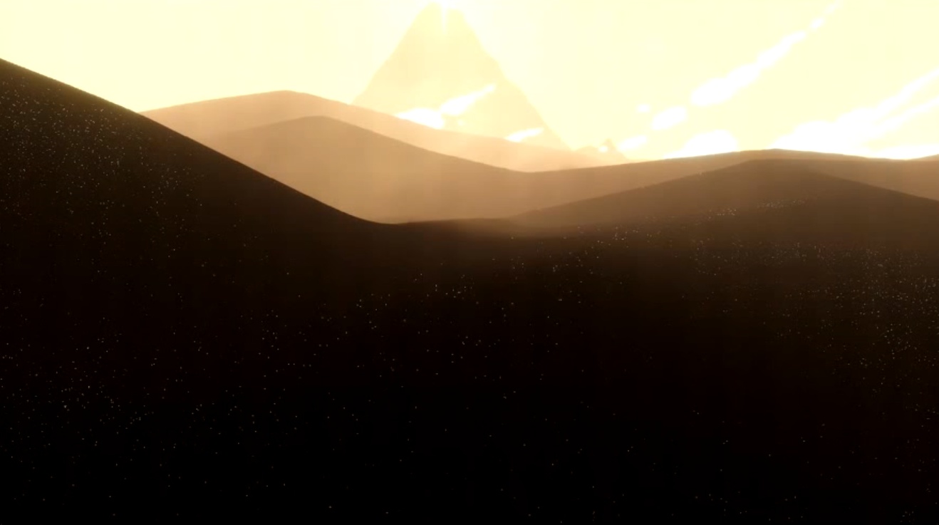
场景最终效果:
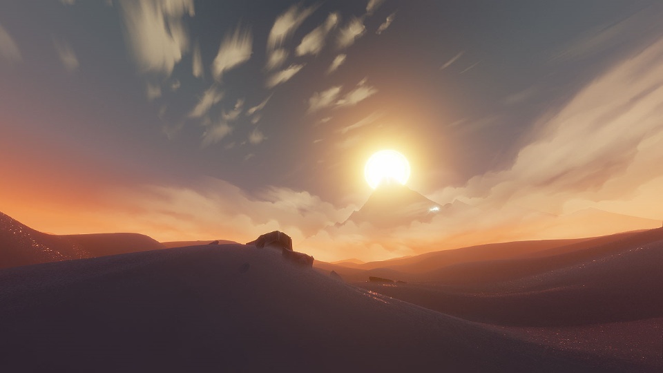
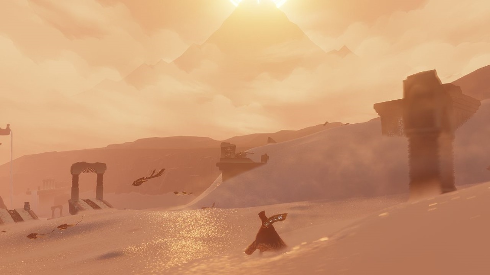
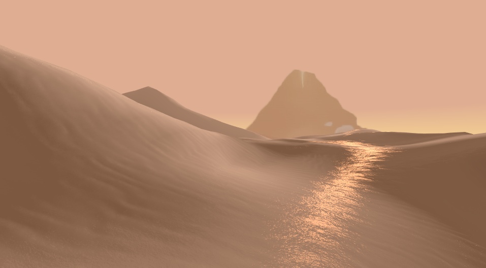
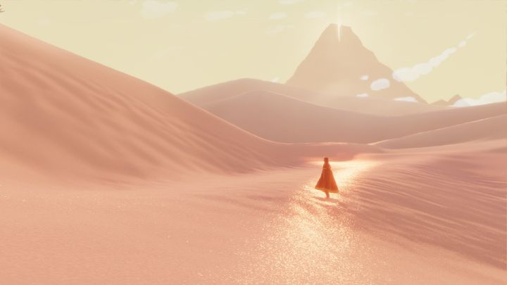
官方参考图,是游戏里的实景:

图片来源:Sand Rendering in Journey
这是GDC的一个讲座,现在已经可以免费观看了。讲座用的PPT下载链接:advances.realtimerendering.com
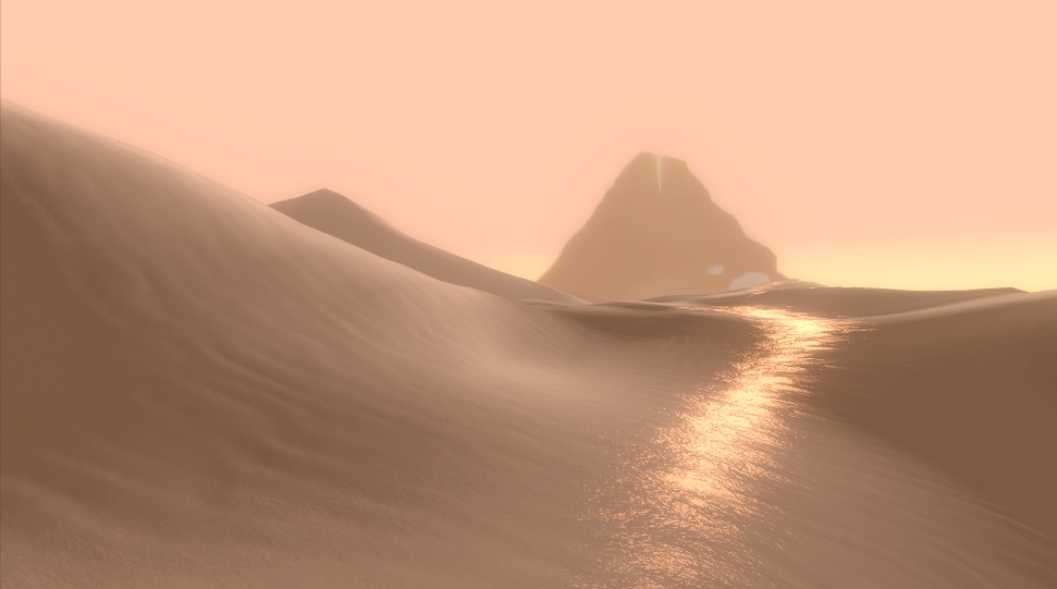
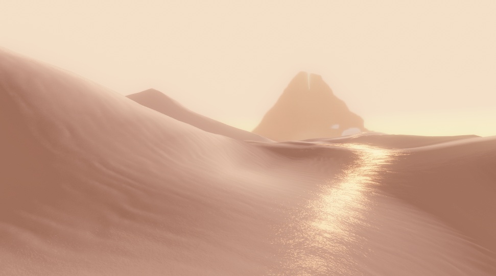
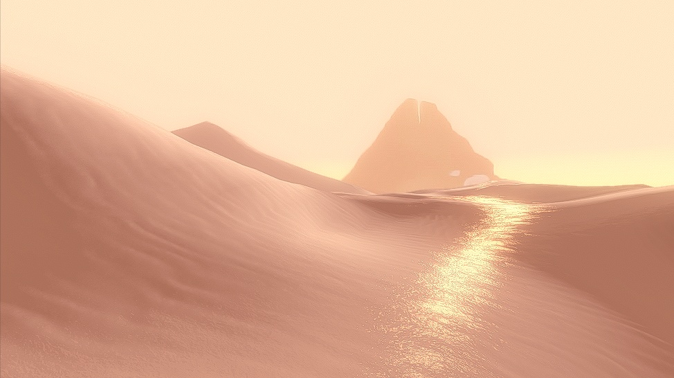
忍不住多方几张官方的插图,因为实在是太漂亮了:
沙子上有blingbling的闪光
为了防止分辨率下降,建议大家下载ppt观看。
好的,鉴赏完毕,接下来是正片。
一、建模 Modeling
讲座里说了是用一个高度贴图height map进行建模。
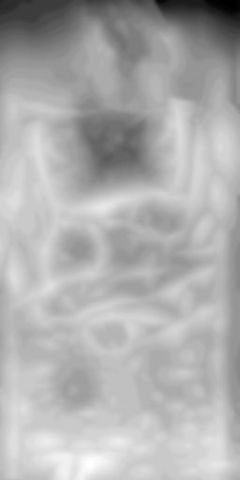
用于建模的height map
基本方法是把图片下载下来之后,在Maya新建一个平面,把面片数调节为50*50:
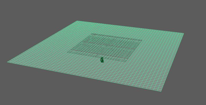
然后打开Surfaces->Sculpt Geometry Tool。打开小窗后,选择Attribute Maps->Import 点击import,然后在路径导航窗口中选中刚才我们使用的height map。导入后每个点的高度变化可能有些小,所以我做了沿Y轴的缩放,完成后效果如下:
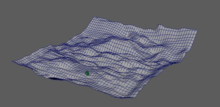
讲座中提到了他们使用B-spline让模型更加平滑。这部分内容主要和建模有关系,这里就不作展开了。
我希望进行渲染的内容为该场景内的一小部分,所以单独为这个镜头建了一个模,如下图:
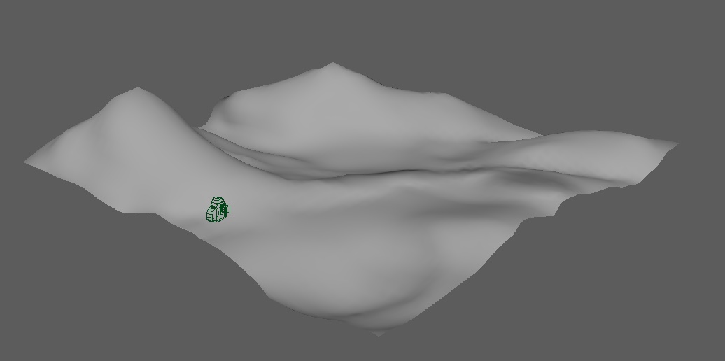
基本上就是用Maya的Sculpting工具修修改改一点点捏出来的。Journey风格的山丘,特点就是山头很尖,一定要尖,做山头的时候可以改用soft select 来调节vertex。
改完后把模型导入Unity,打上背光:
阳光的颜色为(253,208,179)。背景的日光有些丑,所以替换成Jouney的抱抱山和游戏场景中灰黄色的天空。山是游戏截图(估计真实的游戏也就是一个图片( :3 )),天空是一个外部剔除的球体,大概长这样:
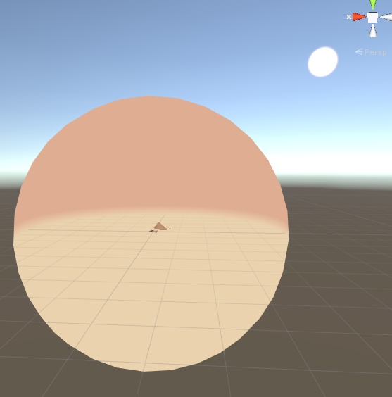
修改过后镜头里的画面:
这里还导入了一个Unity自带的FirstPersonController。这样就可以愉快地在沙丘上跑了。写Shader前的准备工作基本完成。接下来本文就讲座所提及的内容,以倒叙的方式实现(谁叫讲座也是倒过来讲的呢)。
二、基本的明暗 Diffuse
新建一个新的Unlit Shader,建好后加上材质给我们的模型贴上。
首先是一些基本的向量转换的工作,这里贴一下顶点函数:
struct appdata
{
    float4 vertex : POSITION;
    float2 uv : TEXCOORD0;
    float3 normal : NORMAL;
    float4 tangent :TANGENT;
};

struct v2f
{
    float2 uv : TEXCOORD0;
    float3 worldPos : TEXCOORD1;       // position of this vertex in world
    float3 view : TEXCOORD2;           // view direction, from this vertex to viewer
    float3 tangentDir : TEXCOORD3;     // tangent direction in world
    float3 bitangentDir : TEXCOORD4;   // bitangent direction in world

    float3 normal : NORMAL;
    UNITY_FOG_COORDS(5)
    float4 vertex : SV_POSITION;
};
v2f vert (appdata v)
{
    v2f o;
    o.vertex = UnityObjectToClipPos(v.vertex);
    o.uv = v.uv; // here we don't want the main texture to affect the uv
    o.worldPos = mul(unity_ObjectToWorld ,v.vertex).xyz;
    o.view = normalize(WorldSpaceViewDir(v.vertex));
    o.normal = normalize( mul( unity_ObjectToWorld ,  v.normal).xyz ) ;
    o.tangentDir = normalize( mul( unity_ObjectToWorld , float4( v.tangent.xyz, 0) ).xyz );
    o.bitangentDir = normalize( cross( o.normal , o.tangentDir) * v.tangent.w );

    UNITY_TRANSFER_FOG(o,o.vertex);
    return o;
}
视线向量View Direction和法线向量Normal基本上是做渲染必须的。UV的话没有做转换,因为除了MainTexture之外还有贴图需要使用,所以就不作转换了。World Position是一个还算比较常用的向量,所以这里就顺手写了。之后需要使用Normal Map,所以这里需要引入Tangent和Bitangent向量。
基本的明暗关系,作者使用的是OrenNayar模型,具体的代码在PPT里罗列如下:
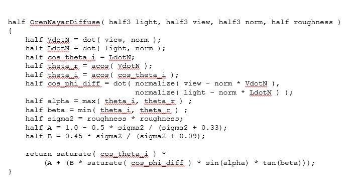
并且用如下方法增加对比度:
最后公式修改如下:
fixed OrenNayarDiffuse( fixed3 light, fixed3 view, fixed3 norm, fixed roughness )
{
    half VdotN = dot( view , norm );

    // the function is modifed here
    // the original one is LdotN = saturate( dot ( light , norm ))
    half LdotN = saturate( 4 * dot( light, norm * float3( 1 , 0.3 , 1 ) ));
    half cos_theta_i = LdotN;
    half theta_r = acos( VdotN );
    half theta_i = acos( cos_theta_i );
    half cos_phi_diff = dot( normalize( view - norm * VdotN ),
                             normalize( light - norm * LdotN ) );
    half alpha = max( theta_i, theta_r ) ;
    half beta = min( theta_i, theta_r ) ;
    half sigma2 = roughness * roughness;
    half A = 1.0 - 0.5 * sigma2 / (sigma2 + 0.33);
    half B = 0.45 * sigma2 / (sigma2 + 0.09);

    return saturate( cos_theta_i ) *
        (A + (B * saturate( cos_phi_diff ) * sin(alpha) * tan(beta)));
}
把这个公式引入,面片着色器修改如下:
fixed4 frag( v2f i ): SV_Target
{
    float4 mainColor = tex2D( _MainTex ,  _MainTex_ST.xy * i.uv.xy + _MainTex_ST.zw );
    float3 lightDirection = normalize( UnityWorldSpaceLightDir( i.worldPos ) );
    float4 lightColor = _LightColor0;
    float3 viewDirection = normalize( i.view );
    float3 halfDirection = normalize( viewDirection + lightDirection);
    float4 ambientCol = unity_AmbientSky;

    float4 diffuseColor = lightColor * mainColor * OrenNayarDiffuse( lightDirection , viewDirection , normal , _Roughness) ;

    return diffuseColor
}
实现效果如下:
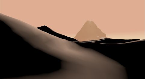
嗯,只有单光源看起来效果不是很好呀,所以多光源支持写起来。
首先在Pass头部,CGPROGRAM之前写上Lighting On。然后在面片着色器里加上循环代码:
for ( int k = 1 ; k < 4 ; ++k ) { // handle up to 4 lights
    float4 lightColork = unity_LightColor[k];
    float3 lightDirectionk = unity_LightPosition[k].xyz - i.worldPos * unity_LightPosition[k].w;
    if ( lightColork.x + lightColork.y + lightColork.z >0 )
    {
        float4 diffuseColk = lightColork * mainColor * ( OrenNayarDiffuse( lightDirectionk , viewDirection ,  normal , _Roughness) );
        diffuseCol += diffuseColk;
    }
}
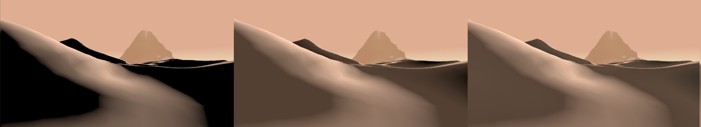
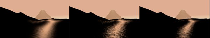
接下来是打光环节,本人也不是专业的灯光,并且在制作过程中灯光也会不断的进行调整。所以这部分仅供参考。主光源(Key Light)不变,是一个从远处往回打的灯光(就是背光的角度),然后Fill Light 打在侧面,做到让场景变得柔和。Rim Light 把山的轮廓强调一下。三个灯光的按添加顺序展示效果如下。
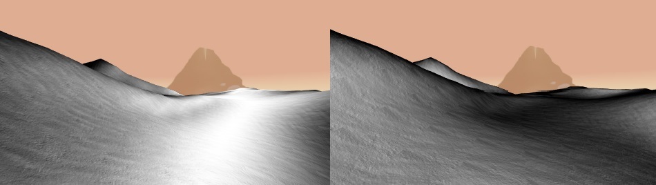
然后是不同Roughness的对比图,左边是Roughness 为0,右边是Roughness为1。好像没什么区别喉。其实更主要的区别会在之后添加specualar的时候看到,在这里我们选择Roughness为0.5。
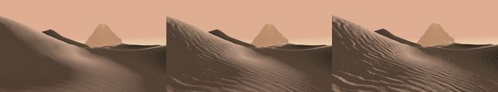
三、沙丘表面纹理 Height Map
原作者的方法是把下述的四个高度贴图(Height Map)整合起来做成沙丘表面的纹理。
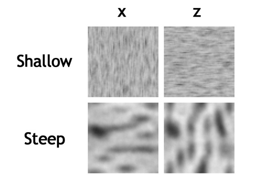
X Z 方向的贴图用于不同法线朝向的表面,Steep 和 Shallow贴图分别用于不同的坡度的表面。(原话为:For each vertex of the detail heightmap, we chose the X- or the Z-column based on which derivative was greater, and we lerped between the shallow and steep rows based on the total steepness of the terrain.)
嗯,这么来说的确有些难理解,实际上我们做一下实验就知道了。
if ( _IsNormalXZ > 0 )
{
    if ( abs( temNormal.z / temNormal.x ) > 1  )
        return float3( abs( temNormal.z )  , 0 , 0  );
    else
        return float3( 0 , 0 , abs( temNormal.x ) );
}
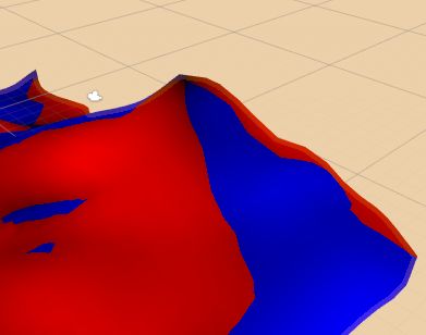
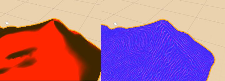
这里根据模型法向的xz分量大小,对模型进行红色和蓝色的着色,可以看到,这样的分类把模型按方向分成了四份。
然后上实景的参考图:
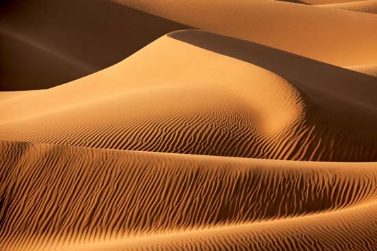
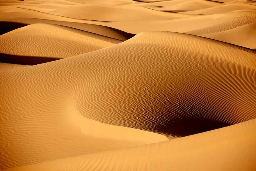
可以看到沙丘的纹路总是沿着沙丘的斜面出现。再看看高度贴图,都是有方向性的,是不是可以理解为,X Z 方向的高度贴图实际上是对应不同方向的纹路?实验的结果如下:
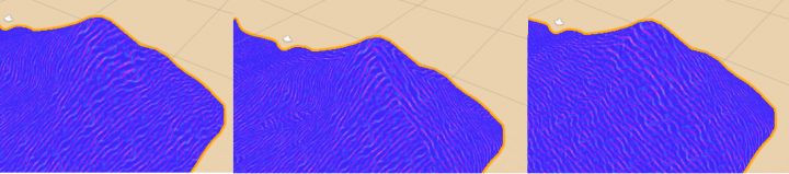
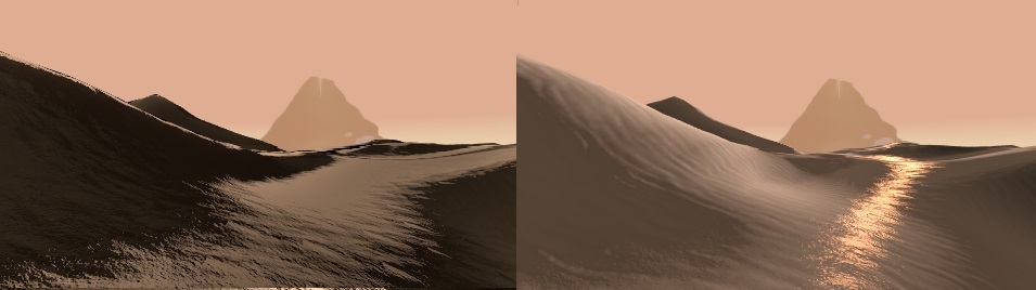
中间是带有纹理方向选择的,左右是只含单个方向的纹理的,对比来看的确中间的纹理比较有立体感。不过这个纹理的衔接处还是比较突兀,所以我用了一个atan函数平滑了一下,代码如下:
float3 GetSurfaceNormal( float2 uv , float3 temNormal )
{
        // get the power of xz direction
    float xzRate = atan( abs( temNormal.z / temNormal.x) ) ;

    float3 steepX = UnpackNormal( tex2D( _NormalMapSteepX , _NormalMapSteepX_ST.xy * uv.xy + _NormalMapSteepX_ST.zw ) ) ;
    float3 steepZ = UnpackNormal( tex2D( _NormalMapSteepZ , _NormalMapSteepZ_ST.xy * uv.xy + _NormalMapSteepZ_ST.zw ) ) ;
    return lerp( steepX , steepZ , xzRate ) ;

}
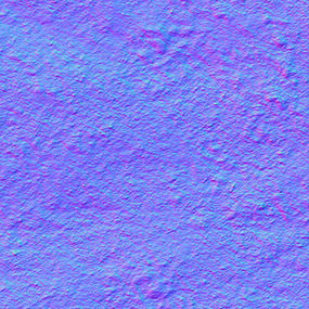
和视频中介绍的高度贴图不同,我使用的是法向贴图,嗯,好像法向贴图的代码写起来比较简单。我用的贴图长这样(都是网上可以搜到的图)
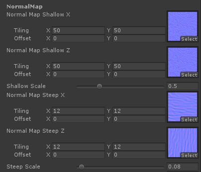
再导入贴图后,要确认贴图的类型(Texture Type)勾选为Normal map。并且使用的时候需要进行一个坐标转换,转换方法如下:
fixed4 frag(v2f i ):SV_Target {
    ...

    // Get the surface normal detected by the normal map
    float3 normalSurface = normalize(GetSurfaceNormal( i.uv  , i.normal ) );

    // 'TBN' transform the world space into a tangent space
    // with the inverse matrix, we can transport the normal from tangent space to world
    float3x3 TBN = float3x3( normalize( i.tangentDir ) , normalize( i.bitangentDir ) , normalize( i.normal ));
    TBN = transpose( TBN);

    // equals to i.tangent * ns.x + i.bitangent * ns.y + i.normal * ns.z
    float3 normal = mul( TBN , normalSurface );

    // Merge the surface normal with the model normal
    normal = normalize( normal * _SurfaceNormalScale + i.normal);

    ...
}
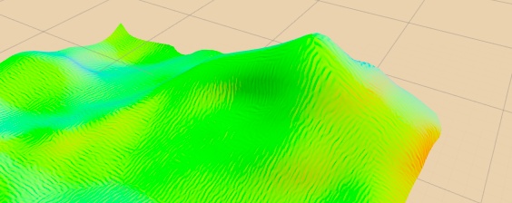
这个转换简单来说就是把在表面坐标系(以Tangent, Bitangent 和 Normal为轴)里的法线向量转换为在世界坐标系(以XYZ为轴)里的法线向量。这个法线方向转换很重要,不然光照效果就会乱了套(不要问我是怎么发现的)。同时这里加入了_SurfaceNormalScale参数,来控制山体表面纹路的深浅。完成后山的法线分布应该是这样的:
之后要做斜度的方向上的分解,和XZ方向类似,同样使用了atan函数进行平滑,具体的代码如下:
float3 GetSurfaceNormal( float2 uv , float3 temNormal )
{
    // get the power of xz direction
    // it repersent the how much we should show the x or z texture
    float xzRate = atan( abs( temNormal.z / temNormal.x) ) ;
    xzRate = saturate( pow( xzRate , 9 ) );

    // get the steepness
    // the shallow and steep texture will be lerped based on this value
    float steepness = atan( 1/ temNormal.y );
    steepness = saturate( pow( steepness , 2 ) );

    float3 shallowX = UnpackNormal( tex2D( _NormalMapShallowX , _NormalMapShallowX_ST.xy * uv.xy + _NormalMapShallowX_ST.zw ) ) ;
    float3 shallowZ = UnpackNormal( tex2D( _NormalMapShallowZ , _NormalMapShallowZ_ST.xy * uv.xy + _NormalMapShallowZ_ST.zw ) ) ;
    float3 shallow = shallowX * shallowZ * _ShallowBumpScale;

    float3 steepX = UnpackNormal( tex2D( _NormalMapSteepX , _NormalMapSteepX_ST.xy * uv.xy + _NormalMapSteepX_ST.zw ) ) ;
    float3 steepZ = UnpackNormal( tex2D( _NormalMapSteepZ , _NormalMapSteepZ_ST.xy * uv.xy + _NormalMapSteepZ_ST.zw ) ) ;
    float3 steep = lerp( steepX , steepZ , xzRate ) ;

    return normalize( lerp( shallow , steep , steepness ) );
}
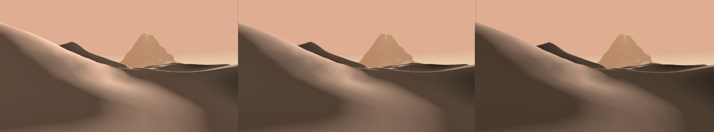
好了,这部分完成以后,场景的渲染效果如下(_SurfaceNormalScale分别为0.1,0.5和2) :
四、风格化高光 Ocean Specualar
首先真的很感慨前辈们在那个光照理论还不很成熟的年代能够做出这么好的艺术效果。在讲座中作者表示这个像海洋高光一样的效果其实是不真实的,但是他们试验之后觉得这个效果好,所以在游戏里就加上了(渲染这种东西有时候真的是凭感觉的呀)。
所谓海面高光是什么意思呢,大概就是这样子的吧:
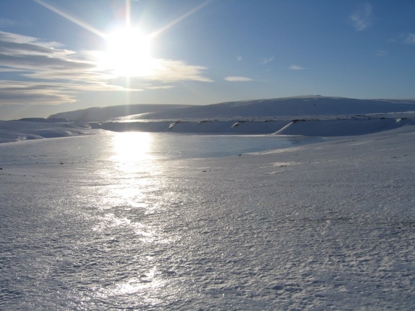
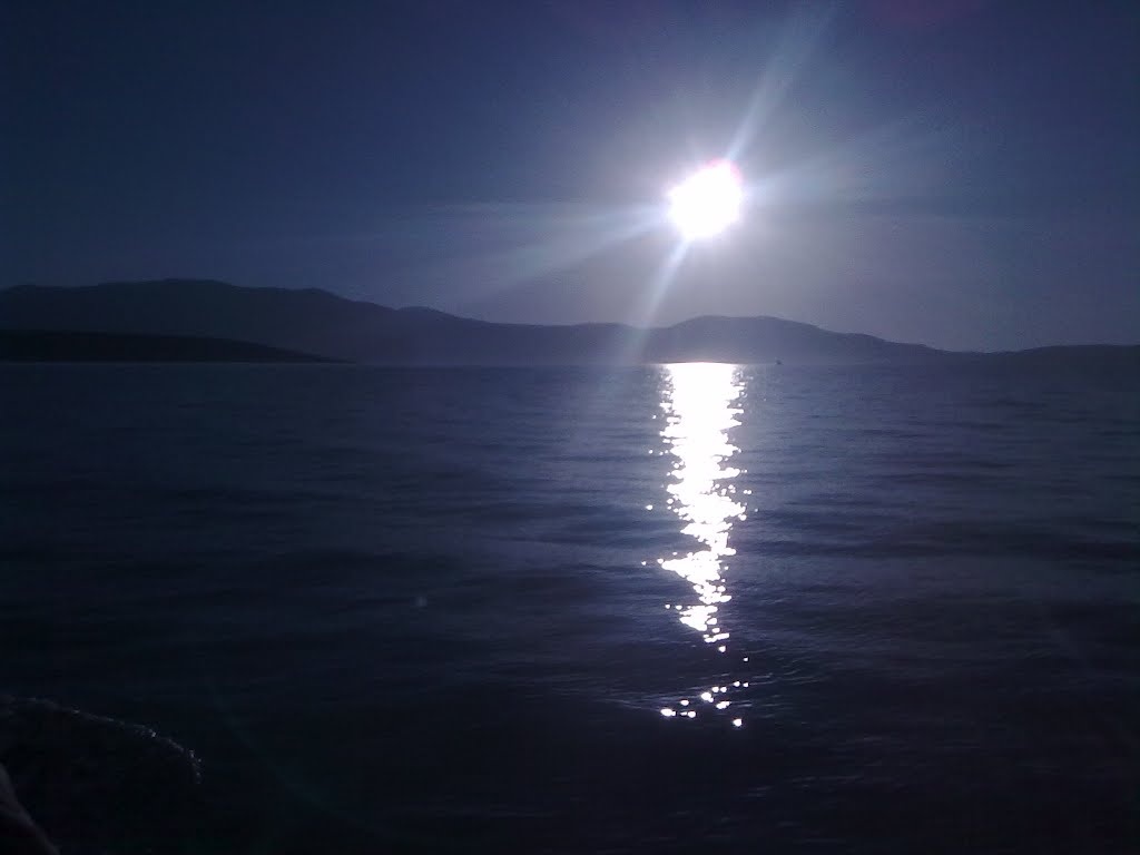
大概就是有中间的一条光束,所以那要怎么实现呢?讲座里没给出具体的算法。所以这部分本人基本靠蒙的。
先是实验了一些Smith GGX,Beckman之类的模型,效果都不是很好。后来突然想起,之前在做水特效的时候,有出现过类似的效果,所以就去查看了一下。发现好像就是最基本的Blinn模型。。。对,就是Blinn,效果反而意外的不错:
float MySpecularDistribution( float roughness, float3 lightDir , float3 view , float3 normal , float3 normalDetail )
{
    // using the blinn model
    // base shine come use the normal of the object
    // detail shine use the normal from the detail normal image
    float3 halfDirection = normalize( view + lightDir);

    float baseShine = pow(  max( 0 , dot( halfDirection , normal  ) ) , 10 / baseRoughness );
    float shine = pow( max( 0 , dot( halfDirection , normalDetail  ) ) , 10 / roughness )  ;

    return baseShine * shine;
}
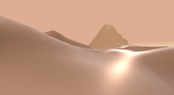
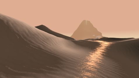
这里的高光分为BaseShine和Shine。BaseShine是用来确定高光的边界,使用的法线是之前所说的加上Normal Map之后的Normal。shine是用来做纹理,就是做出那种波光粼粼的效果,这里的Normal实际上是使用了一个新的细节纹理法向贴图,并且把贴图缩小来做到细小的纹理效果。不过由于素材的原因,和目标效果始终有一些微小的差距。最终效果如下:
使用的细节纹理:
和之前的diffuse叠加(线性叠加)在一起后,效果如下:
后期处理的时候加一些Bloom效果会进一步提高整体的视觉效果,先卖个关子~
然后我也试着结合BRDF的知识手动添加了一些高光,但是效果也一般,所以这里就不展开说明了,只是上个效果图:
五、贴图过滤 Anisotropic Filtering(略)
这部分的作用是让在远距离的贴图能够更加清晰,一个比较典型的例子是这样的(注意看远处部分的瓷砖):
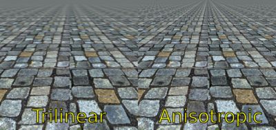
这个算法在Unity里已经被整合好了。在Editor->Quality Settings里面有一个Anisotropic Textures的选项用于开关这个效果,默认打开。这部分也就不详细说明了(感觉当年Journey团队真辛苦,连这个也要自己做)。
六、亮片效果 Glitter
亮片效果是什么呢,就是在沙子上blingbling的那种效果:
单拎出来是这样滴:
按照讲座中作者的话来说,他们理解的亮片就是沙堆中有一部分的沙子正好朝向观察者,那么它们就会朝你发射光线,从而产生blingbling的效果。嗯,理论上是这样没错,但是这叫我怎么写呀。关于Glitter的效果可以参考2017的siggraph里的这篇文章:
http://blog.selfshadow.com/publications/s2017-shading-course/dreamworks/s2017_pbs_dreamworks_notes.pdf
个人总结下来,做Glitter效果可以分为两个步骤,一个是噪点的制作,另一个是高光的制作。
在讲座中,作者讲了他们的高光制作的过程,一个灰常任性的制作过程。因为传统的高光函数为的参数为pow(N·H,n),这个公式在上面的海洋高光中也用到了。作者觉得Glitter需要的更多关于人眼方位的信息,所以就把这个公式里的H换成了V,即观察者方向向量。
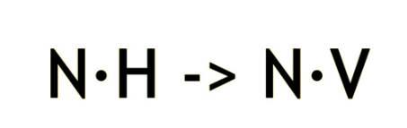
两者的对比大概是这样的:
不过光有高光函数是不够的,因为闪光点并不是在沙子上均匀的出现的,相反,它们的分布十分随机,这就需要我们设计一个随机分布的函数来获取这些亮点分布的位置。在讲座中没有说明噪点函数的生成具体方法,所以接下来又要进入瞎蒙时间。
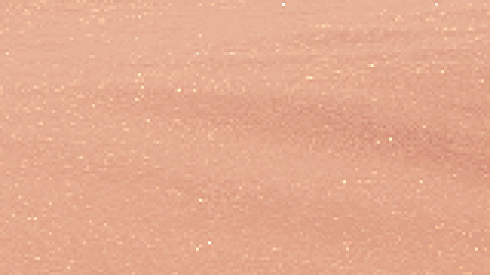
首先准备一个噪点图,这次我用的图大概长这样:
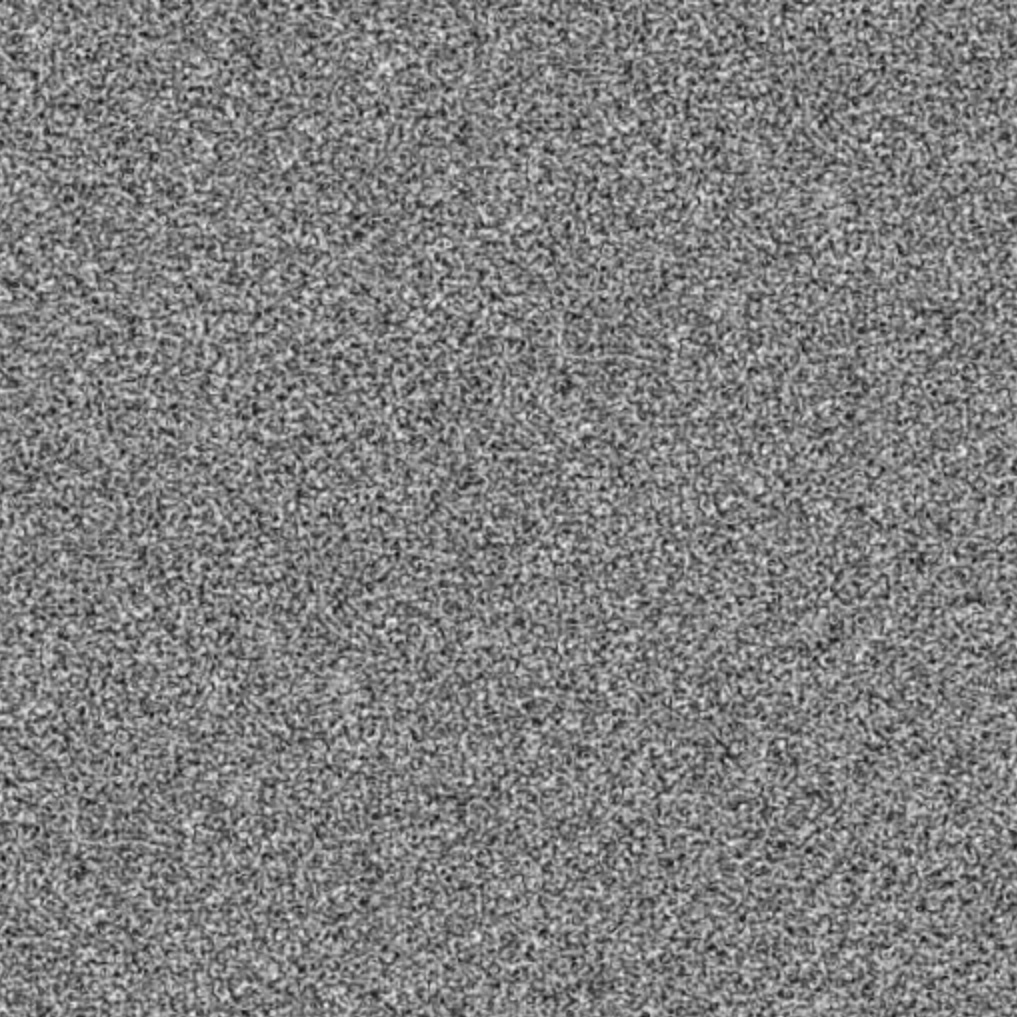
然后根据这个噪点图,进行噪点的处理。这个函数是凭经验试验出来的,放在这里仅供参考:
float3 GetGlitterNoise( float2 uv )
{
    return tex2D( _GlitterTex , _GlitterTex_ST.xy * uv.xy + _GlitterTex_ST.zw ) ;
}
float GliterDistribution( float Glitterness , float3 lightDir , float3 normal, float3 view , float2 uv , float3 pos )
{
        ...
    float p1 = GetGlitterNoise( uv + float2 ( 0 , _Time.y * 0.0005 + view.x * 0.0050  )).r;
    float p2 = GetGlitterNoise( uv + float2 ( _Time.y *0.001 , _Time.y * 0.001 + view.y * 0.003 )).g;

    float sum = p1 * p2;
        // making discrete noise
    float glitter = max( 0 , pow( sum , _Glitterness ) * _GlitterMutiplyer - 0.5 ) * 2;

        ...
}
制作噪点的效果:
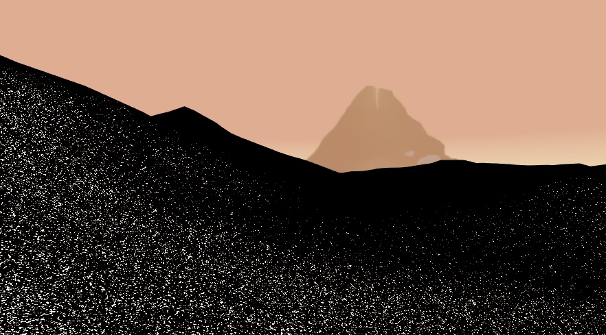
颗粒感可以做到这样,而且在场景走起来的时候blingbling的感觉还是有的,不过闪光点的密度太大了。之前不是有一个用N·V求出来的分布函数嘛,那我们就把它拿来当做蒙版吧(这一趴系完全的瞎蒙,如果有读者知道具体的算法可以留言处告诉我)。完整的代码是这样的:
float GliterDistribution( float3 lightDir , float3 normal, float3 view , float2 uv , float3 pos )
{
    float specBase = saturate( 1 - dot( normal , view ) * 2 );
    float specPow = pow( specBase , 10 / _GlitterRange );

    //  A very random function to modify the glitter noise
    float p1 = GetGlitterNoise( uv + float2 ( 0 , _Time.y * 0.001 + view.x * 0.006 )).r;
    float p2 = GetGlitterNoise( uv + float2 ( _Time.y * 0.0006 , _Time.y * 0.0005 + view.y * 0.004  )).g;
    float sum = 4 * p1 * p2;

    float glitter = pow( sum , _Glitterness );
    glitter = max( 0 , glitter * _GlitterMutiplyer - 0.5 ) * 2;

    float sparkle = glitter * specPow;

    return sparkle;
}
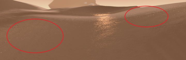
添加了Glitter效果的沙丘:
七、其他
Mipmap
这是一个在Texture上的类似于LOD的系统,在讲座中有提到,这个技术能够让沙子颗粒感更强。这里就略过了。
距离雾 Fog
通过调用宏实现,在新建Shader的时候自带的代码,这里沿用下来。
后期调整 Post Effect
目前来说渲染的场景长这样:
和Journey游戏里的场景好像还有点距离,不过其实只要加上一些些Camera特效就会好很多了。
首先是Bloom,把高光部分的光照质感做出来。这里使用的是Unity官方出的Post Processing Stack插件(Post Processing Stack - Asset Store)。
然后调一下颜色:
这里是把Post Processing里的ToneMap 调成Natural,并添加了一个LUT:

最后使用的是一个叫Beautify的插件(Beautify - Asset Store),添加了一下锐化的效果,并且增加了一点对比度:
对比一下官方提供的图片:
本工程已经同步到Github上了,链接:
https://github.com/AtwoodDeng/JourneySand
这是侑虎科技第369原创文章,感谢作者在木(邓佳迪)供稿。欢迎转发分享,未经作者授权请勿转载。如果您有任何独到的见解或者发现也欢迎联系我们,一起探讨。(QQ群:793972859)
作者知乎:https://zhuanlan.zhihu.com/zaimu,同时,作者也是U Sparkle活动参与者哦,UWA欢迎更多开发朋友加入U Sparkle开发者计划,这个舞台有你更精彩!